
DIY Midi Controller Drum Set: Turn your old Rock Band drums into something awesome!
Project name: Arduino Midi Drums
Difficulty: Intermediate
Cost: $60-80 (<$10 if you already have drums and an Arduino!)
An Arduino is possibly the most versatile board you can use if you’re interested in building your own midi controller.
Buying a midi drum set, such as the Alesis DM6, will easily cost you over $300. If you’re just looking for a fun studio toy to play around with, that kind of price point might seem unreasonable.
What if I was to say you can build your own midi drum set with velocity-sensitive pads for practically nothing? That is exactly what we’ll be talking about today!
Recommended course: The DIY MIDI Controller Course. If you want to become a master at making your own custom controller, this is the course for you! Packed with 11 action-packed modules that include downloadable images, schematics, sample code, and libraries. Even if you’re a hobby musician that doesn’t know anything about circuitry or programming, this course breaks it down to an understandable sense.
What you’ll need:
- Arduino Uno
- 1.0M Ohm resistor
- 220 Ohm resistor
- Proto Board
- Midi Port – Can be obtained for free from Guitar Hero or Rock Band drums!
- Male pin headers
- (optional) Midi-to-usb cable – If you don’t have an audio interface, you need some way to connect your drums to your computer!

What’s inside a Rock Band/Guitar Hero drum set?
First, let’s go over how video-game drum sets work.
Each pad registers feedback from a basic device called a piezo sensor. A piezoelectric sensor measures changes in pressure and converts it to an electrical charge.
When you hit a drum pad, the harder you hit it, the more electricity will pass through. If you hit the pad lightly, a much weaker signal would pass through.
Piezo sensors are the best choice for midi drums because we’ll be able to easily make each pad velocity-sensitive based on the signal that comes from the piezo.
How this midi build will work:
Our midi controller needs to do two things:
- Detect when, and how hard, you hit the pads
- Convert that signal to midi and output it to a midi output
Arduino shields are boards that you can plug into the top of your Arduino. There are a whole bunch of different shields for sale that do many different things, but for this build, we’ll be making our own simple one.
The shield will allow us to plug in all of the piezo sensors from the Rock Band drums. The reason we needed protoboard and male header pins is to build the shield.
Now all you need to do is rig-up the midi output port. In the video, Evan explains how you can salvage and mod the Rockband drum’s midi input to work in this build.
After you finished doing all of that, give yourself a pat on the back. :)
Time to upload code to the Arduino! Evan wrote publicly available code for you to take advantage of! You can check it out if you scroll down a bit to the code section of this article.
Video Tutorial
https://www.youtube.com/watch?v=vi-w_WqJjzQ
Video courtesy of Evan Kale
Big thanks to Evan for letting me use the video and schematics in this article!
Schematics

This first image illustrates how we would create midi drums if we were using plain-old piezo sensors instead of making a custom Arduino shield and using the video-game drum set’s piezos.
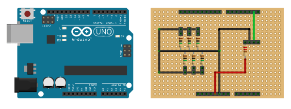
This schematic shows how the shield is wired. Make sure to checkout the video for further explanation.
Code
For more information about the use of this code as well as direct support from the creator, checkout the Arduino Midi Drums Github page!
/*
 * Copyright (c) 2015 Evan Kale
 * Email: EvanKale91 (at) gmail.com
 * Website: www.ISeeDeadPixel.com
 *          www.evankale.blogspot.ca
 *
 * This file is part of ArduinoMidiDrums.
 *
 * ArduinoMidiDrums is free software: you can redistribute it and/or modify
 * it under the terms of the GNU General Public License as published by
 * the Free Software Foundation, either version 3 of the License, or
 * (at your option) any later version.
 *
 * This program is distributed in the hope that it will be useful,
 * but WITHOUT ANY WARRANTY; without even the implied warranty of
 * MERCHANTABILITY or FITNESS FOR A PARTICULAR PURPOSE.  See the
 * GNU General Public License for more details.
 *
 * You should have received a copy of the GNU General Public License
 * along with this program.  If not, see <http://www.gnu.org/licenses/>.
 */

//Piezo defines
#define NUM_PIEZOS 6
#define SNARE_THRESHOLD 30     //anything < TRIGGER_THRESHOLD is treated as 0
#define LTOM_THRESHOLD 30
#define RTOM_THRESHOLD 30
#define LCYM_THRESHOLD 100
#define RCYM_THRESHOLD 100
#define KICK_THRESHOLD 50
#define START_SLOT 0     //first analog slot of piezos
#define START_NOTE 70    //starting note

//MIDI defines
#define NOTE_ON_CMD 0x90
#define NOTE_OFF_CMD 0x80
#define MAX_MIDI_VELOCITY 127

//MIDI baud rate
#define SERIAL_RATE 31250

//Program defines
//ALL TIME MEASURED IN MILLISECONDS
#define SIGNAL_BUFFER_SIZE 100
#define PEAK_BUFFER_SIZE 30
#define MAX_TIME_BETWEEN_PEAKS 20
#define MIN_TIME_BETWEEN_NOTES 50

//map that holds the mux slots of the piezos
unsigned short slotMap[NUM_PIEZOS];

//map that holds the respective note to each piezo
unsigned short noteMap[NUM_PIEZOS];

//map that holds the respective threshold to each piezo
unsigned short thresholdMap[NUM_PIEZOS];

//Ring buffers to store analog signal and peaks
short currentSignalIndex[NUM_PIEZOS];
short currentPeakIndex[NUM_PIEZOS];
unsigned short signalBuffer[NUM_PIEZOS][SIGNAL_BUFFER_SIZE];
unsigned short peakBuffer[NUM_PIEZOS][PEAK_BUFFER_SIZE];

boolean noteReady[NUM_PIEZOS];
unsigned short noteReadyVelocity[NUM_PIEZOS];
boolean isLastPeakZeroed[NUM_PIEZOS];

unsigned long lastPeakTime[NUM_PIEZOS];
unsigned long lastNoteTime[NUM_PIEZOS];

void setup()
{
  Serial.begin(SERIAL_RATE);

  //initialize globals
  for(short i=0; i<NUM_PIEZOS; ++i)
  {
    currentSignalIndex[i] = 0;
    currentPeakIndex[i] = 0;
    memset(signalBuffer[i],0,sizeof(signalBuffer[i]));
    memset(peakBuffer[i],0,sizeof(peakBuffer[i]));
    noteReady[i] = false;
    noteReadyVelocity[i] = 0;
    isLastPeakZeroed[i] = true;
    lastPeakTime[i] = 0;
    lastNoteTime[i] = 0;
    slotMap[i] = START_SLOT + i;
    noteMap[i] = START_NOTE + i;
  }

  thresholdMap[0] = KICK_THRESHOLD;
  thresholdMap[1] = RTOM_THRESHOLD;
  thresholdMap[2] = RCYM_THRESHOLD;
  thresholdMap[3] = LCYM_THRESHOLD;
  thresholdMap[4] = SNARE_THRESHOLD;
  thresholdMap[5] = LTOM_THRESHOLD;
}

void loop()
{
  unsigned long currentTime = millis();

  for(short i=0; i<NUM_PIEZOS; ++i)
  {
    //get a new signal from analog read
    unsigned short newSignal = analogRead(slotMap[i]);
    signalBuffer[i][currentSignalIndex[i]] = newSignal;

    //if new signal is 0
    if(newSignal < thresholdMap[i])     {       if(!isLastPeakZeroed[i] && (currentTime - lastPeakTime[i]) > MAX_TIME_BETWEEN_PEAKS)
      {
        recordNewPeak(i,0);
      }
      else
      {
        //get previous signal
        short prevSignalIndex = currentSignalIndex[i]-1;
        if(prevSignalIndex < 0) prevSignalIndex = SIGNAL_BUFFER_SIZE-1;                 unsigned short prevSignal = signalBuffer[i][prevSignalIndex];                  unsigned short newPeak = 0;                  //find the wave peak if previous signal was not 0 by going         //through previous signal values until another 0 is reached         while(prevSignal >= thresholdMap[i])
        {
          if(signalBuffer[i][prevSignalIndex] > newPeak)
          {
            newPeak = signalBuffer[i][prevSignalIndex];
          }

          //decrement previous signal index, and get previous signal
          prevSignalIndex--;
          if(prevSignalIndex < 0) prevSignalIndex = SIGNAL_BUFFER_SIZE-1;           prevSignal = signalBuffer[i][prevSignalIndex];         }                  if(newPeak > 0)
        {
          recordNewPeak(i, newPeak);
        }
      }

    }

    currentSignalIndex[i]++;
    if(currentSignalIndex[i] == SIGNAL_BUFFER_SIZE) currentSignalIndex[i] = 0;
  }
}

void recordNewPeak(short slot, short newPeak)
{
  isLastPeakZeroed[slot] = (newPeak == 0);

  unsigned long currentTime = millis();
  lastPeakTime[slot] = currentTime;

  //new peak recorded (newPeak)
  peakBuffer[slot][currentPeakIndex[slot]] = newPeak;

  //1 of 3 cases can happen:
  // 1) note ready - if new peak >= previous peak
  // 2) note fire - if new peak < previous peak and previous peak was a note ready
  // 3) no note - if new peak < previous peak and previous peak was NOT note ready

  //get previous peak
  short prevPeakIndex = currentPeakIndex[slot]-1;
  if(prevPeakIndex < 0) prevPeakIndex = PEAK_BUFFER_SIZE-1;           unsigned short prevPeak = peakBuffer[slot][prevPeakIndex];       if(newPeak > prevPeak && (currentTime - lastNoteTime[slot])>MIN_TIME_BETWEEN_NOTES)
  {
    noteReady[slot] = true;
    if(newPeak > noteReadyVelocity[slot])
      noteReadyVelocity[slot] = newPeak;
  }
  else if(newPeak < prevPeak && noteReady[slot])   {     noteFire(noteMap[slot], noteReadyVelocity[slot]);     noteReady[slot] = false;     noteReadyVelocity[slot] = 0;     lastNoteTime[slot] = currentTime;   }      currentPeakIndex[slot]++;   if(currentPeakIndex[slot] == PEAK_BUFFER_SIZE) currentPeakIndex[slot] = 0;   } void noteFire(unsigned short note, unsigned short velocity) {   if(velocity > MAX_MIDI_VELOCITY)
    velocity = MAX_MIDI_VELOCITY;

  midiNoteOn(note, velocity);
  midiNoteOff(note, velocity);
}

void midiNoteOn(byte note, byte midiVelocity)
{
  Serial.write(NOTE_ON_CMD);
  Serial.write(note);
  Serial.write(midiVelocity);
}

void midiNoteOff(byte note, byte midiVelocity)
{
  Serial.write(NOTE_OFF_CMD);
  Serial.write(note);
  Serial.write(midiVelocity);
}
Final Notes
So there you have it!
I hope you had success in building your own DIY midi drum set! Let me know how it went in the comment section below!
If you are a music producer and want valuable tips and tricks to improve your productions, sign up for my mailing list down below!
Leave a Comment
17 comments
what if serial data is sent to USB…then converted to midi..using hairless midi converter or serial to midi converter software? will the drums run?
If you’re using a software instrument or VST plugin on your computer and it is compatible with MIDI (99.9% of them are) then a serial-to-MIDI software would work.
Another option, which is rewarding but equally challenging, is to flash the HIDUINO firmware on your Arduino. This would make it so that the Arduino sends MIDI data instead of standard serial. The only downside is that you couldn’t program your Arduino via USB with the firmware active and you’d have to use an ICSP programmer instead.
Let me know if you have any other questions/confusions! I’d be happy to help:)
but if hinduino firmware burnt on uno r3 etc..WILL WE NEED TO ALTER THE MIDIDRUM SKETCH CODE? IF YES,HOW?
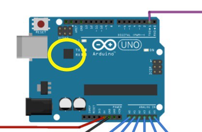
Nope. Notice how the TX of the Arduino goes to the midi port. With Hiduino, the serial output of TX is sent through the usb port instead. The code will work perfectly without any changes. Also keep in mind that Hiduino is not being burnt onto the Atmega328 chip. It is burnt onto the smaller chip near the USB port(as seen in the image below).
Thanks for the valuable tips. but I will go the simple wa. The serial signals do, however, travel through the USB port by default. But that data is serial..since hairless is freeware..it will convert it to midi data however….this is simple way. correct me if wrong
Nothing wrong with the easy way! Yep; using software to convert the serial data to MIDI data is your best route. When you plug in the Arduino, with its default firmware, it shows up as a regular serial device. Even though it sends serial data at a baud rate of 31250 just like a regular midi controller, it is still not recognized as a MIDI controller by your computer. That’s where the software does its job.
my intention is FL STUDIO drum trigers with velocity.
Nice!
Hey how do we connect the midi wire to the computer and what is the software i should use to give out audio output
To connect MIDI, you’ll need one of these handy little cables. By a piece of software that provides audio output, are you referring to a drumming software? If so, you have a lot of options. For free, you can check out PC Drummer(Windows) or the free version of DrumCore(Mac). I heard good things about both but admittingly haven’t tested them. You can check out the paid drum software I prefer in my article titled ‘5 of the Best Drum Machine VST plugins in Existence‘.
there is a Roland’ serial to midi driver. can we use it with mididrum thru USB without updating original firmware?
Can I connect 8 or 10 pads to this board?
If you purchase the Arduino Mega instead of the Arduino Uno, you will be able to use up to 16 pads. The Arduino Uno only supports up to 6. :)
Is there a way to have a high hat open close pedal?
As long as your DAW/plugin/software supports that, you can. You just need to map the correct MIDI note with your Arduino. Hope that helps!
I don’t know why, I cannot hear sound from GarageBand and the software don’t interact, but it interact in hairless-midiserial.
The video is no longer available on YouTube, can it be found elsewhere?