
DIY Midi Foot Controller Using An Arduino Uno: The Best Way To Build Custom Foot Controllers
Midi foot controllers are a game-changing piece of equipment for guitarists and musicians alike.
Maybe you don’t want to spend $150+ on a foot controller.
Maybe you haven’t found a foot controller that does everything you desire.
Wouldn’t it be cool to build your own?
In this article, we’ll be building a DIY midi foot controller that was inspired by an article on the very cool and helpful site, ‘Randumb Page’. The article there was good, but I wanted to make it even more clear and easy-to-follow.
Let me know what you think of this build in the comment section below!
Make sure to share this article on social media if find it helpful, awesome, or both!
Recommended course: The DIY MIDI Controller Course. If you want to become a master at making your own custom controller, this is the book for you! Packed with 11 action-packed chapters that include downloadable images, schematics, sample code, and libraries. Even if you’re a hobby musician that doesn’t know anything about circuitry or programming, this book breaks it down to an understandable sense.
An Overview Of What We’ll Be Making:
What we’ll be making is a very functional midi foot controller.
It is made using my favorite board of all time, the Arduino Uno.
Basically, you’ll be making a very customizable midi foot controller.
The enclosure can be made out of just about anything. I’ll leave that up to your interpretation. Also, let me know if building custom enclosures is something you’d be interested in learning more about in the comment section below.
Materials:
- Arduino Uno
- 5 Switches
- 3 potentiometers (for volume and wah)
- LCD to display info information such as volume level, stompbox status, and your current patch name.
- 3 10k resistors
- 1 LED
- MIDI – IN , and MIDI OUT ports.
- Spare wires
<– Let me save you some time! Click the orange shopping cart on the left to add all of the materials to your cart on Amazon.com.

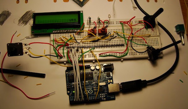
Step 1: The Circuitry
The first step is to get everything wired-up correctly.
Refer to the super-handy diagram above. Everything is color coded to make your life a bit easier.
Is the image not big enough for you to read? Click here for a larger version.
Step 2: Uploading the Code
Connect your Arduino Uno to your computer via usb as normal.
Open up the Arduino IDE software. (If you don’t have it, you can download it here)
Copy & paste the code from down below into your software. Compile the code and you shouldn’t get any errors.
Project Code
#include <LiquidCrystal.h>
LiquidCrystal lcd(7, 6, 5, 4, 3, 2);
#define LED 13 // LED pin on Arduino board
#define switch1 8 // 1st Switch
#define switch2 9 // 2nd Switch
#define MIDI_COMMAND_CONTROL_CHANGE 0xB0
//Variables
int switch1LastState = 0;
int switch1CurrentState = 0;
int switch2LastState = 0;
int switch2CurrentState = 0;
//Potentiometer controlls (Analog)
int volumePot = A3;
int volumePrev = 0;
int volumeCurrent = 0;
int levelPot = A4;
int levelPrev = 0;
int levelCurrent = 0;
int wahPot = A2;
int wahLevelPrev = 0;
int wahLevelCurrent = 0;
// the format of the message to send Via serial
typedef union {
struct {
uint8_t command;
uint8_t channel;
uint8_t data2;
uint8_t data3;
} msg;
uint8_t raw[4];
} t_midiMsg;
void blinkLed(byte num) { // Basic blink function
for (byte i=0;i<num;i++) {
digitalWrite(LED,HIGH);
delay(100);
digitalWrite(LED,LOW);
delay(100);
}
}
void setup() {
pinMode(LED, OUTPUT);
pinMode(switch1, INPUT);
pinMode(switch2, INPUT);
pinMode(volumePot, INPUT);
pinMode(levelPot, INPUT);
pinMode(wahPot, INPUT);
lcd.clear();
lcd.print("ranDumb-MIDI"); // Starting message
delay(5000);
Serial.begin(115200);
blinkLed(3); // Setup sucess indicator
}
void loop() {
t_midiMsg midiMsg; // MIDI message for Switch 1
switch1CurrentState = digitalRead(switch1); // reading Switch 1
switch2CurrentState = digitalRead(switch2); // reading Switch 2
// SWITCH 1 CONTROL START
if (switch1CurrentState == 1){ // If Switch is true
if(switch1LastState == 0){ // If Switch1 was not pressed continously
midiMsg.msg.command = MIDI_COMMAND_CONTROL_CHANGE; // this sends Channel info along with Control Change message
midiMsg.msg.channel = 1; // Data 1
midiMsg.msg.data2 = 1; // Data 2
midiMsg.msg.data3 = 0;
lcd.clear();
lcd.print("sw1 Msg1");
/* Send MIDI Message */
Serial.write(midiMsg.raw, sizeof(midiMsg));
blinkLed(2); }
}
if (switch1CurrentState == 0){ // If Switch1 was false
if(switch1LastState == 1){
midiMsg.msg.command = MIDI_COMMAND_CONTROL_CHANGE; // this sends Channel info along with Control Change message
midiMsg.msg.channel = 1; // Data Not Channel
midiMsg.msg.data2 = 1; // Velocity
midiMsg.msg.data3 = 127; /* Velocity */
lcd.clear();
lcd.print("sw1 Msg2");
/* Send note on */
Serial.write(midiMsg.raw, sizeof(midiMsg));
blinkLed(2); }
}
switch1LastState = switch1CurrentState;
// SWITCH 1 CONTROL END
// SWITCH 2 CONTROL START
if (switch2CurrentState == 1){
if(switch2LastState == 0){
midiMsg.msg.command = MIDI_COMMAND_CONTROL_CHANGE;
midiMsg.msg.channel = 1; // Data
midiMsg.msg.data2 = 2; // Velocity
midiMsg.msg.data3 = 0; /* Velocity */
lcd.clear();
lcd.print("Sw2 Msg1 ");
/* Send note on */
Serial.write(midiMsg.raw, sizeof(midiMsg));
blinkLed(2); }
}
// SWITCH 2 Second State Control
if (switch2CurrentState == 0){
if(switch2LastState == 1){
midiMsg.msg.command = MIDI_COMMAND_CONTROL_CHANGE;
midiMsg.msg.channel = 1;
midiMsg.msg.data2 = 2;
midiMsg.msg.data3 = 127; /* Velocity */
lcd.clear();
lcd.print("Sw2 Msg2 ");
/* Send note on */
Serial.write(midiMsg.raw, sizeof(midiMsg));
blinkLed(2); }
}
switch2LastState = switch2CurrentState;
// SWITCH2 CONTROL END
volumeCurrent = analogRead(volumePot)/8;
// levelCurrent = analogRead(levelPot)/8;
wahLevelCurrent = analogRead(wahPot)/8;
if(volumePrev != volumeCurrent)
{
midiMsg.msg.command = MIDI_COMMAND_CONTROL_CHANGE;
midiMsg.msg.channel = 1;
midiMsg.msg.data2 = 7;
midiMsg.msg.data3 = volumeCurrent; // Velocity
Serial.write(midiMsg.raw, sizeof(midiMsg));
blinkLed(2);
// Printing Switch number and data MIDI data that is sent to the LCD screen
lcd.clear();
lcd.setCursor(0,0);
lcd.print("Volume");
lcd.setCursor(0,1);
lcd.print(volumeCurrent);
volumePrev = volumeCurrent;
blinkLed(4);
}// End Of Volume Control Loop
/* // I don't have the Level control so I just Quoted out this part of the code .
//Level control loop
if(levelPrev != levelCurrent)
{
midiMsg.msg.command = MIDI_COMMAND_CONTROL_CHANGE;
midiMsg.msg.channel = 1;
midiMsg.msg.data2 = 0x0C;
midiMsg.msg.data3 = levelCurrent;
Serial.write(midiMsg.raw, sizeof(midiMsg));
blinkLed(2);
// Printing Switch number and data MIDI data that is sent to the LCD screen
lcd.clear();
lcd.setCursor(0,0);
lcd.print("Level");
lcd.setCursor(0,1);
lcd.print(levelCurrent);
levelPrev = levelCurrent;
blinkLed(4);
}// End Of Level Control Loop
*/
// Wah Control Loop
if(wahLevelPrev != wahLevelCurrent)
{
midiMsg.msg.command = MIDI_COMMAND_CONTROL_CHANGE;
midiMsg.msg.channel = 1;
midiMsg.msg.data2 = 0x0B;
midiMsg.msg.data3 = wahLevelCurrent; /* Velocity */
/* Send note on */
Serial.write(midiMsg.raw, sizeof(midiMsg));
blinkLed(2);
// Printing Switch number and data MIDI data that is sent to the LCD screen
lcd.clear();
lcd.setCursor(0,0);
lcd.print("Wah");
lcd.setCursor(0,1);
lcd.print(wahLevelCurrent);
wahLevelPrev = wahLevelCurrent;
blinkLed(4);
}// End Of wah Control Loop
}
Step 3: The Boot-loader
In order to make the Arduino show up like a proper midi device, you will need a boot-loader.
An alternative to this would be to use serial-to-midi software. That is a bit lame and not as fun, so I’d recommend going with the boot-loader option.
First, download the corresponding USB Midi Firmware file. (aka the boot-loader) There’s even some useful sample code provided as well. This project basically takes the code and tweaks it to be more suitable for a DIY midi foot controller.
Unfortunately, it seems like the website with those firmware files went down. These days, I use Hiduino anyway. Give it a shot! If you’re confused at all with it, Hiduino is covered in-depth in my DIY MIDI Controller course.
Follow this guide from Arduino. It will walk you through everything you need to know about uploading the midi hex file to your Arduino.
Step 4: Testing Time!
If you have successfully made it to this step, congrats! The hardest part is over.
Everything should now work perfectly.
Beware of Loose Connections!
If you notice your knobs are outputting some random midi signals, it could be because of a loose or faulty connection. Arduinos tend to continually search for inputs if they aren’t connected correctly.
Final Notes:
So There you have it!
Hopefully your DIY midi foot controller is functioning perfectly.
If you have any questions, leave a comment below.
Leave a Comment
22 comments
Hi. Thank you for this nice tuto!
I will love to try it out, but I´m having trouble finding out the pinouts for the LCD display.
I got another type than yours – with a keypad shield.
I have no problem with D4 – D7 and RS. I´m just not sure of the rest of the connections from Arduino to the LCD display. (Marked with yellow)
Can you please help me with that?
Thanks in advance :-)
Hey Jens! I appreciate your question. Refer to the image I attached to this comment for a pinout of the used LCD. Let me know if you run into any other problems. I’d be happy to help!
Hi Doug
Thank you very much! :-)
Anytime!
Hey!
Thanks a lot for this. Really cool!
I have a question and need some help. I don’t know where to start.
Basically I want to make my Arduino a really basic midi-send device. I want four buttons that only will send the same as any midi-controller would. Bank 0 ch1, bank 0 ch2 and so forth.
Do you know how to do this?
Best
/Rob
Sounds like you just need a midi controller with 4 buttons? The build will be similar to the one mentioned in this article, just missing a few bells and whistles. Then you would just map the midi buttons to your bank controls.
Hope this helps!
I’m on it right now.
Thanx
Awesome! Come back here if you ever need help:) I’m actually going to be launching a book soon on the A-Zs of building custom midi controllers. If you’re interested, you can sign up for updates here. Thanks for reading!
-Doug
Hi,
Great tutorial!
Can we bypass the midi sockets and connect directly using USB on Arduino to control the software?
Thanks!
Your computer would still recognize your Arduino as a standard serial device instead of a MIDI device.
There are two ways to get past this:
1. Download software that can convert serial data to MIDI. There are a few choices available that can do this.
2. Flash the HIDUINO firmware to the 16u2 chip on your Uno. This will make your Arduino show up as an actual MIDI controller when you plug it into the computer. You will need an icsp programmed to flash the firmware. You would also need an icsp programmer to upload code to your Arduino since your Arduinos’s USB port won’t work for programming anymore. I recommend the USBTINYISP. It’s a very cheap icsp programmer that works great!
Great! Will try once I have the chance.
Thanks so much!
No problem dude! Come back if you ever run into any problems. I’d be happy to help! ?
Great Project.
Would the same project (or rather what Robert described further up) work as well with an arduino nano? I haven’t used those before.
If I just want to toggle 24 patches with a few buttons…
With the nano, it may be doable if you remove the LCD display from the equation. If you’d like to keep the LCD you might have to use a shift register.
The LCD uses 6 digital inputs and there are 7 digital inputs on the nano. I believe you can also use the analog inputs as “digital” inputs, however, I have not yet tried that.
Ah okay. Well I would need the display.
Arduinos aren’t that expensive though, I might give it a go in the near future.
As a bonus tip, if you didn’t already know, you can purchase Arduino clones for $4-5 on AliExpress that function exactly the same as the $20 Arduino. Since Arduino is open source hardware, you’ll find a lot of inexpensive clones available.
Hi from Russia! Great job! Want to make something like this and has one question: what if i’ll need more buttons? Is it possible?
Hey, Den! Russia’s awesome:) To get more buttons, you have two choices.
1). Purchase an Arduino with more digital pins. (The Arduino Mega has a ton!)
2). Use a shift register. In chapter 5 of the DIY MIDI Controller Bible I talk about using a 74HC595 chip to get, essentially, an unlimited amount of inputs.
Let me know if you have any more questions! :D
Hi! I was wondering how this would work with foot pedal potentiometers instead of knobs.
Great article, btw.
Appreciate it Anthony! You should look for foot pedal potentiometers with three wires like this one.
Those type of foot pedals work exactly the same as normal potentiometers.
You might want to consider checking out DIYMIDIController.com. Great course there that’s appropriately called ‘The DIY MIDI Controller Course‘ – it goes over everything you’ll want to know in detail. :)
All the best,
-Doug
How would you do that controller with arduino nano and one and an ic2 on lcd?
HI :)
Good job :) But not evertyhing is clear for me ;) I try to build MIDI switch like this:
https://www.youtube.com/watch?v=z4jOhp0Z0G4&list=LLEAraodebD8NUGHokeepUWw&t=13s&index=4
Could you help mi something?; ) Thnx anyway ;)