
Arduino Midi Controller Tutorial: Adding Buttons, Switches, And Knobs
Last time, we learned how to make a very basic Arduino midi controller.
It wasn’t user controllable, BUT we learned an essential lesson: How to send a midi signal from an Arduino out of a midi port and to our computer.
Today, we’ll be learning how to make an actual midi controller. It can be controlled by knobs (potentiometers), faders, buttons, or in the example we’ll be talking about, switches.
First of all, I want to thank Bharat of Randumb for providing this information. Make sure to checkout his site here for more awesome projects.
First, we’ll start by making this midi controller work over usb serial. Once you get that working flawlessly, you can apply the skills learned in my previous article on sending midi signals.
Let me know what you think of this build in the comment section below!
Recommended course: The DIY MIDI Controller Course. If you want to become a master at making your own custom controller, this is the course for you! Packed with 11 action-packed modules that include downloadable images, schematics, sample code, and libraries. Even if you’re a hobby musician that doesn’t know anything about circuitry or programming, this course breaks it down to an understandable sense.
What you need
The hardware needed is pretty basic. If you are going to be converting this project to full-on midi, you’ll additionally need some midi ports.
In this example we are using switches, but feel free to use anything else! Buttons work exactly the same.
An LED, a breadboard, and an enclosure are optional. If you are still in the experimental phase of your midi-mayhem, you can get away without those.
Hardware
- Arduino Uno
- 2x Switches, potentiometers, buttons, or faders
- Spare wires
- (Optional) LED
- (Optional) Bread Board
- (Optional) Enclosure
Software
- Arduino IDE (Link)
- Serial to MIDI converter (Link)
- Midi YOKE Virtual MIDI port (Link)
- MIDI-OX (to monitor midi signals) (Link)
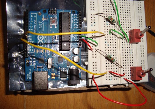
Schematics

Here is the diagram for this project. Keep in mind that the schematic will vary if you decide to implement a midi port into this project.
A breadboard is used in the schematic. Although it is listed as an optional item, I’d still recommend purchasing one. They’re cheap and they make prototyping a hell of a lot easier.
Code
#define LED 13 // LED pin on Arduino board
#define switch1 10 // 1st Switch
#define switch2 9 // 2nd Switch
#define MIDI_COMMAND_CONTROL_CHANGE 0xB0
#define MIDI_COMMAND_NOTE_ON 0x90
#define MIDI_COMMAND_NOTE_OF 0x80
//Variables
int switch1LastState = 0;
int switch1CurrentState = 0;
int switch2LastState = 0;
int switch2CurrentState = 0;
// the format of the message to send Via serial
typedef union {
struct {
uint8_t command;
uint8_t channel;
uint8_t data2;
uint8_t data3;
} msg;
uint8_t raw[4];
} t_midiMsg;
void blinkLed(byte num) { // Basic blink function
for (byte i=0;i<num;i++) {
digitalWrite(LED,HIGH);
delay(50);
digitalWrite(LED,LOW);
delay(50);
}
}
void setup() {
pinMode(LED, OUTPUT);
pinMode(switch1,INPUT);
pinMode(switch2, INPUT);
Serial.begin(115200);
blinkLed(3);
}
void loop() {
t_midiMsg midiMsg1; // MIDI message for Switch 1
t_midiMsg midiMsg2; //MIDI message for Swtich 2
switch1CurrentState = digitalRead(switch1);
switch2CurrentState = digitalRead(switch2);
if (switch1CurrentState == 1){
if(switch1LastState == 0){
midiMsg1.msg.command = MIDI_COMMAND_CONTROL_CHANGE;
midiMsg1.msg.channel = 1;
midiMsg1.msg.data2 = 1;
midiMsg1.msg.data3 = 0; /* Velocity */
/* Send note on */
Serial.write(midiMsg1.raw, sizeof(midiMsg1));
blinkLed(2); }
}
switch1LastState = switch1CurrentState;
if (switch2CurrentState == 1){
if(switch2LastState == 0){
midiMsg2.msg.command = MIDI_COMMAND_CONTROL_CHANGE;
midiMsg2.msg.channel = 2;
midiMsg2.msg.data2 = 2;
midiMsg2.msg.data3 = 0; /* Velocity */
/* Send note on */
Serial.write(midiMsg2.raw, sizeof(midiMsg2));
blinkLed(2); }
}
switch2LastState = switch2CurrentState;
}
Turning your Arduino into an actual midi device
Like I mentioned earlier, you can apply the knowledge from my Sending Midi Signals article to convert this project into a true midi controller.
Bharat had an interesting way to turn your Arduino into a midi device without the need of a midi port.
Here’s how it works:
Basically, we’re going to be making the Arduino show up as an HID midi device.
This is possible by installing midi firmware on your Arduino’s Atmeg8u2 chip. Keep in mind that using this method will be a pain if you plan to go back and revise your code. You’d have to reinstall the previous firmware and then go back to the midi firmware all over again.
Final Notes
voilà!!
Hopefully by now your midi controller is fully functioning.
Don’t hesitate to leave a comment down below if you can’t get your Arduino midi controller to function properly. I’d be happy to answer!
Leave a Comment
2 comments
thanks for the article. It would be very nice to read an article on how to add the tactile buttons since it seems a lot different than the potentiometer you seem to use in the example. I followed your first article on using the midi port with the arduino and i was thrilled when it worked :)
Glad you enjoyed it, Colin! By tactile buttons, you’re referring to regular on/off buttons like these, correct? If so, our partner, DIY MIDI Controller, offers a free sample course teaching you how to create a simple one-button MIDI controller.